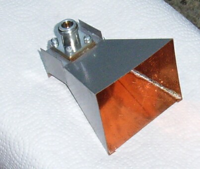
The 5.7 and 3.4GHz Feed Horns incorporate a wave guide to co-ax (N Type) transition. If you need to communicate with the author you will find my e-mail address in graphic (not machine readable) form on my home page.
|
|
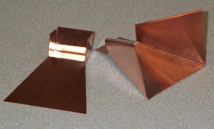
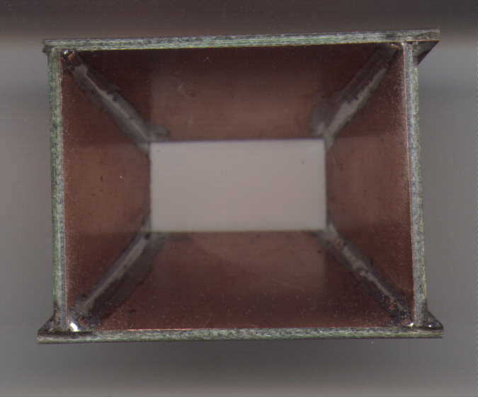
| Template Right click and "save as" to download | Ready for assembly after cutting and folding |
|
|
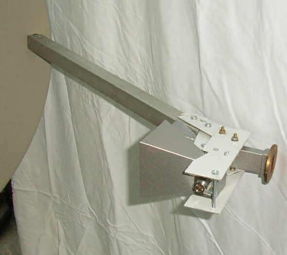
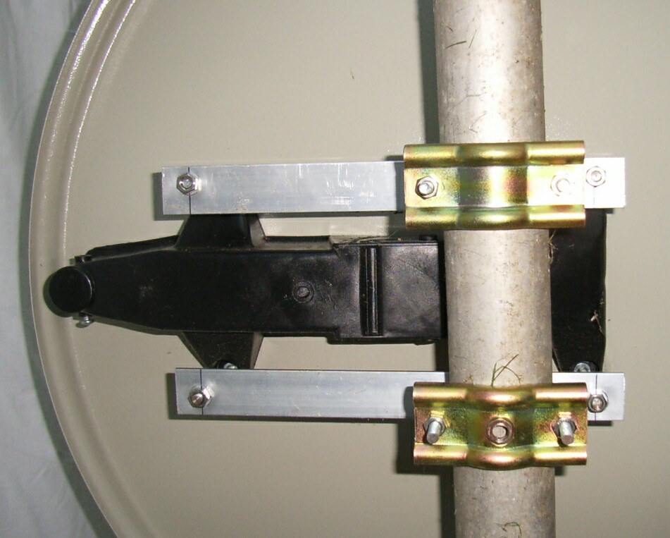
| A two band mounting arrangement on a LIDL dish. There are a number of advantages when the dish is mounted on its side | These include ease of mounting, no elevation adjustment is needed, the Offset between bands is only in azimuth. It is possible to feed the 10GHz horn with entirely rigid waveguide using two H-plane bends and if the waveguide is run from above the dish it will be self draining. |
|
|
| Template. Right click and "save as" to download | The 3.4GHz horn is made in 4 parts |
Some construction notes:- As I have to hand bend all the corners, I found it useful to make a jig consisting of two strips of about 20mm x 5-10mm steel about 150mm long, both drilled with a few ( 4 or more) mating holes at points along their length with one side clearance the other side tapped. This can then be used to clamp the copper sheet while bending it. A third piece is used to fold the copper and allow it to be hammered for a tight bend without denting the copper too badly. Drill the probe hole to 4mm diameter initially while the copper is flat so that it can be accurately positioned. When it comes to soldering the seams a supply of small G or toolmakers clamps, to hold the parts together and act as a heat sinks on the previously soldered seams to prevent them from coming unsoldered, will be useful. I find a hot air "gun" (Paint stripper) is the best way to solder these horns. I used solder paste for the N-Type mounting plate. Hold it in place with an M4 bolt and nut with a spring to keep it tight to the waveguide as the solder flows. Open this hole to 10mm after soldering (very carefully in no more than 0.5mm steps as you will be holding the horn by the thin copper walls which you will not want to bend or dent) . Make sure the M3 screws fixing the N-Type are not too long or they'll dent the copper wg. The probe dimensions given should result in a return loss of 20dB or better which is quite good enough. The probe can be tuned by adjusting it’s length but this can be time consuming . The N socket should be of the type that has a flat back plate such as SUHNER 23N-50-23. Otherwise the back of the socket must be machined flat. Finally, to prevent corrosion, I coat the inside of the horn with "spray on" flux (using a brush to distribute it evenly) and spray the outside with Hammerite.
10GHz Feed Horn for 0.7f/D (offset) dishes.
|
|
| Template. Right click and "save as" to download | The 10GHz horn is made in 4 parts |
The 10GHz Horn is constructed to fit onto WG16. When it comes to soldering the horn onto the waveguide the thermal conductivity of solid copper becomes a disadvantage so the template is for construction from copper laminate. The E-Plane sides are cut to size while the H-plane sides are slightly oversize to provide an overlap. Score the true dimension onto the copper from the template though. All the parts should be chamfered at the waveguide end to provide a flat butt joint. Assemble with the front edges flush taking care to keep the assembly rectangular. Once soldered the waveguide end can be carefully filed flat in readiness for soldering to the waveguide. I find it best to use a hot air (paint stripper) gun for soldering. Clamp the waveguide vertically with some thermal insulation between it and the vice or clamp. Heat the cleaned waveguide until (a very small amount of) solder flows on the end surface of the waveguide. Carefully position the horn. If you are quick it should be possible to run around the inside seam with a previously heated iron and some solder to complete the joint. Surplus solder can be filed away. The joint is still very fragile at this stage so after removing any dirt or flux I apply a fillet of “Chemical metal” (Plastic padding or similar filler) to the outside of the joint to provide strength.
Return to Home page